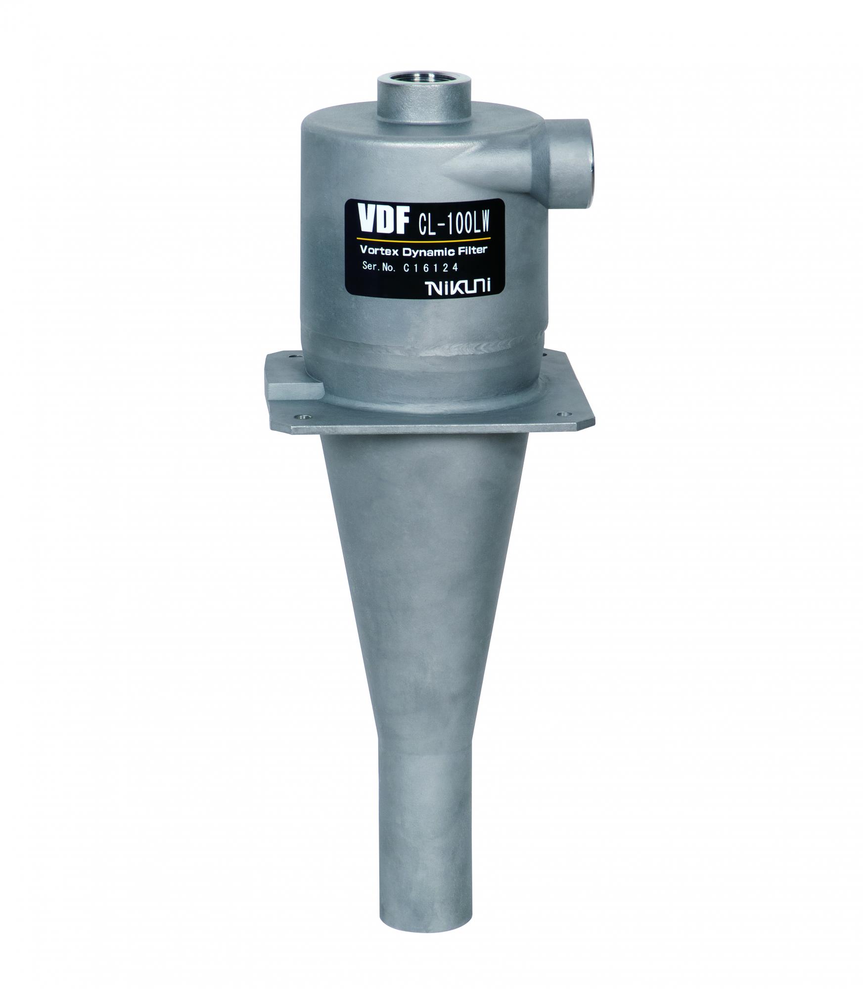


Vortex Dynamic Filter is a highly efficient, media free coolant filtration system which achieves filtration through centrifugal force eliminating the need for disposable paper or cartridge filters
Fluid containing sludge flows from the supply pump into the VDF via the side port and through the inlet,
which is positioned tangential to the periphery at the top of the separator.The fluid flows along the
inner wall of the cyclone and the pressure energy is converted into rotational energy. Whilst turning
under the strong centrifugal force, the heavier sludge descends the tapered body towards the narrow
nozzle in the base of the VDF. After passing the nozzle the sludge is discharged into the sludge pod.
The discharged sludge rapidly loses its rotational force, is collected in the sludge pod and collects
until discharging, either manually or via a solenoid valve. Any ultra fine sludge which is unable to
generate sufficient centrifugal force and descend down the inner wall of the separator, is discharged
along with the cleaned fluid from the top port. During this process an area of low pressure is present
in the center of the separator.

| Pump head (m) |
CL-20LW | CL-30LW | CL-50LW | CL-70LW | CL-100LW | CL-200LW | CL-300LW | CL-1000LW | ||||||||
|---|---|---|---|---|---|---|---|---|---|---|---|---|---|---|---|---|
| Fluid supply (L/min) |
Clean liquid flow (L/min) |
Fluid supply (L/min) |
Clean liquid flow (L/min) |
Fluid supply (L/min) |
Clean liquid flow (L/min) |
Fluid supply (L/min) |
Clean liquid flow (L/min) |
Fluid supply (L/min) |
Clean liquid flow (L/min) |
Fluid supply (L/min) |
Clean liquid flow (L/min) |
Fluid supply (L/min) |
Clean liquid flow (L/min) |
Fluid supply (L/min) |
Clean liquid flow (L/min) |
|
| 15 | 20 | 18 | 25 | 22 | 40 | 36 | 63 | 59 | 82 | 78 | 165 | 160 | 245 | 240 | 855 | 855 |
| 20 | 22 | 20 | 30 | 25 | 45 | 40 | 70 | 65 | 95 | 90 | 185 | 180 | 280 | 275 | 1000 | 1000 |
| 30 | 27 | 24 | 35 | 30 | 55 | 50 | 85 | 75 | 110 | 100 | 230 | 210 | 335 | 300 | 1100 | 1100 |
| Pump head (m) |
CL-20LW | CL-30LW | CL-50LW | CL-70LW | CL-100LW | CL-200LW | CL-300LW | |||||||
|---|---|---|---|---|---|---|---|---|---|---|---|---|---|---|
| Fluid supply (L/min) |
Clean liquid flow (L/min) |
Fluid supply (L/min) |
Clean liquid flow (L/min) |
Fluid supply (L/min) |
Clean liquid flow (L/min) |
Fluid supply (L/min) |
Clean liquid flow (L/min) |
Fluid supply (L/min) |
Clean liquid flow (L/min) |
Fluid supply (L/min) |
Clean liquid flow (L/min) |
Fluid supply (L/min) |
Clean liquid flow (L/min) |
|
| 15 | 19 | 17 | 22 | 19 | 34 | 30 | 55 | 48 | 73 | 67 | 140 | 130 | 210 | 185 |
| 20 | 22 | 20 | 24 | 21 | 39 | 35 | 63 | 55 | 86 | 80 | 165 | 152 | 240 | 215 |
| 30 | 26 | 24 | 29 | 26 | 48 | 43 | 77 | 68 | 102 | 96 | 202 | 185 | 295 | 268 |
Depending on the pump performance and piping installation, amount of clean fluid may differ. Please
pay attention when making selection.
The recommended supply pressure for VDF is in the range of 0.2 to 0.3 MPa.